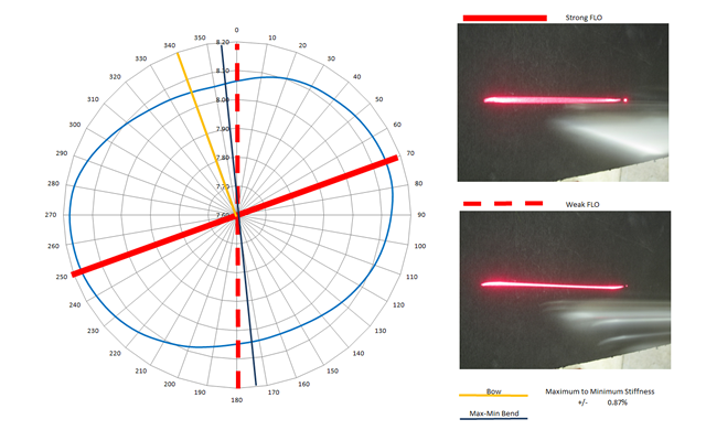
This is a study of the radial properties of 6 shafts I did in 2011. It is a supplement to a video published that year about golf shaft alignment. I have learned a great deal about golf shafts since that publications and my view of shaft alignment has radically changed.
I discussed the measurement techniques I use to explore radial consistency of golf shafts. I explain bow, flow and the proper way to measure radial consistency of a golf shaft. Golf shaft manufacturing has improved over time. With current manufacturing practices golf shaft spine no longer exists in premium shafts. The only benefit to alignment is the profit made by those selling the service.
View this video as part of my history as I explored and learned about golf shafts. I made this a long time ago and no longer agree with the conclusions. I do not recommend any form of shaft alignment. I do check shafts for radial consistency. Those that are round get used, those that are not get returned to the manufacturer.
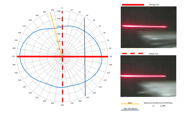
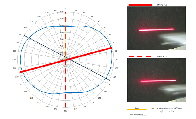
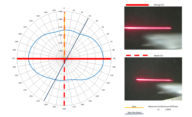
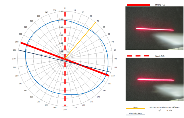
The charts below show the effectiveness of the Three Point bearing tool, often referred to as a spine tool and a tip weight laser tool in locating the radial stiffness high and low points of a driver shaft. The tip laser device, often refereed to as Flat Line Oscillation FLO or Vertical Oscillation Plane VOP is an effective tool for finding the stiff and weak planes of the shaft. This can be accomplished by the club maker by FLOing the shaft in a CPM device and noting the CPM of the shaft at each of the two FLO planes. The stiff and weak planes are easily identified. If the difference is beyond 2 CPM, the quality of that shaft is marginal. Beyond 4 CPM the shaft is garbage and should have been culled at the factory. Discarding bad shafts is a cost to a manufacturer. Some companies choose to sell products that should have been scrapped.
The bearing based Spine tools show the bow of shafts and have little value in identifying the stiff and weak planes of a shaft.
This study was inspired by the writing of my friend, Dave Tutelman. This link is his article on the subject, http://www.tutelman.com/golf/shafts/allAboutSpines.php
The data show below is an interesting illustration of golf shaft properties. The scale of measured stiffness, the blue curve, had to be radically enhanced to see the change in stiffness around the shaft. I preserved the illustrations from an old blog because it illustrates the relationship between clamped shaft oscillation and radial stiffness. Take note, where the is a flat line oscillation, there is also a second flat line oscillation about 90 degrees away.
The measurements are as follows.
STIFFNESS
The stiffness of the shaft as measured every 10 degrees. The shaft was clamped at the butt end, the tip was deflected 1″, the load cell was set to zero. The shaft was then deflected 5″. This method measures the stiffness of the material without any affect from any bowing or curvature in the shaft. The readings are shown as the blue line. The readings were smoothed to eliminate measurement ‘noise’.
VERTICAL OSCILLATION
A weighted laser tip was attached to the shaft. The shaft was deflected 3″ and released. The laser trace was recorded in a 5 second timed exposure. The shaft was rotated until a stable plane of oscillation was found. The photo of the trace is shown to the right of the shaft. The shaft was then turned 90 degrees and the second stable plane was located. The solid red line shows the stable plane of the shaft closest to the stiff side of the shaft. The dashed red line, the stable plane that was on the softer side of the shaft.
BOW
Using a three point bending tool the bow of the shaft was located. This tool is a pair of bearings in a tube. The shaft is inserted into the ID of the bearings and a third bearing is used to deflect the shaft. The shaft turns to the bowed side to minimize the stress of the loading force. The Bow is shown as a Yellow line.
TIP DEFLECTION
The shaft was inserted into a machining chuck which can be rotated. Two pieces of card stock were bent 90 degrees and set against each side of the tip. The shaft was rotated. The cardstock was pushed away from the shaft as the tip moved during the rotation. The points of maximum deflection to the right and left were noted and indicated by the black line.
