Adjusting 3 Point Bend Measurements for Tube Deformation
By Russ Ryden, Fit2Score, A Dallas Fort Worth Club Fitter & Club Maker
The Golf Center at the Highlands, Carrollton Texas
EI profiling is one of several methods used by shaft designers and club fitters to understand a golf shaft. In several research papers on golf shafts, 3 point EI bend testing is faulted for failing to account for tube deformation under load. With the assistance and coaching from Dave Tutelman I began a study of shaft deformation in a 3 point bending test. That study, which lasted over a year, is now complete. I have developed a simple measuring process to compensate for tube deformation in 3 point EI measurements.
These illustrations show a cross section of the shaft measuring process and graphically illustrates the deformation issue.
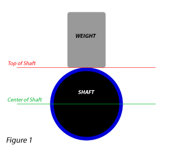 Figure 1: The typical 3 point measuring system uses a gauge positioned at the top of the shaft. A preload is applied to the shaft, and the measuring gauge is set to zero.
This set of drawings is vastly exaggerated to illustrate the point. In fact the deformation of the shaft is a very small percentage of the bending of the shaft.
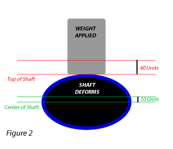 Figure 2: When load is applied to the shaft, It bends. Golf shafts are hollow tubes, not only do they bend, they also deform, becoming oval. Deformation is a function of the hoop strength of the shaft. In linear bend testing, the oval deformation is a source of error. We want to measure the bending of the centerline of the shaft shown here as 10 units. We actually measure both ovaling and bending.
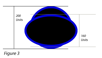 Figure 3: Remember, In these drawings, the ovalization of the shaft is vastly exaggerated. The top to bottom dimension of the loaded shaft changes by 40 units. Part of that dimension, 30 units is the deformation of the shaft. Not the bending of the shaft.
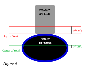 Figure 4: The correction; measure both the top wall and the bottom wall of the shaft to calculate how much the shaft deformed. Subtract half of that difference from the top wall measurement. In this exaggerated illustration, the actual centerline deflection is 10 units. That is determined by subtracting half the difference between the top and bottom wall deflection from the top wall deflection.
This deformation occurs in three places, the left support, the center press and the right support. To accurately determine the centerline EI, all three deformations must me measured and accounted for in the calculation of EI.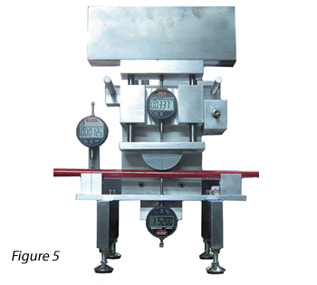
Figure 5: This is an EI instrument built for researching and understanding tube deformation during 3 point loading. A gauge under the shaft measures deformation at the bottom wall. The difference between the top and bottom gauge is ovalization of the shaft. A third gauge measures deformation at the beam support. After studying many shafts, we can now forecast deformation from hoop stiffness alone.
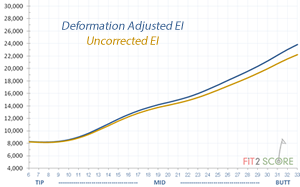 The ovalizing of the shaft shown above is exaggerated for the purpose of the illustration. In fact it is typically less that 2% near the tip and as much as 20% near the butt. The correction does not change the shape of the EI graphics. It does modify the slope. The butt section of shafts is revealed as stiffer than uncorrected top wall deformation data. As you can see here, the subtle stiffness changes shown in inch by inch 3 point profiling are apparent in both the uncorrected and adjusted graphics. Those stiffness bumps that are the essence of feel and performance are apparent in both graphics. The adjusted graphics make butt stiffness more accurate going forward.
The three gauge instrument shown above is time consuming to use. It is now available for purchase. We knew at the onset of this research project that deformation was going to correlate to the hoop strength measurements we are already taking with a single gauge instrument.
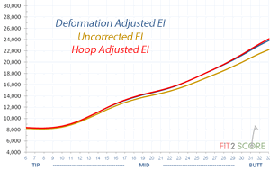 Applying a multiplier to the hoop deformation we have been measuring, we correct the EI data. In this illustration you can barely see a difference between the 4 point measured deformation and the 1 point + hoop adjusted deformation. The measured deformation is done at both the tip and butt supports and the press. The hoop deformation is done under the press, applying the load to the shaft while it is firmly supported on a block of metal.
A great number of shafts with different materials have been run through the 4 point measurement process. A universal correction factor has been shown to apply universally to all shafts we have tested. Hoop deformation against a solid block is a method that accurately corrects top wall measurement to center line bending. This should forever end the critique of the accuracy of 3 point measurement of golf shafts. I am indebted to my friend Dave Tutelman for his guidance and assistance as we worked on this project for over a year.


